Summary
In a volumetric rendering application, an image is generated by shooting rays of light into the volume. As each light ray passes through the voxels making up the volume, a portion of the ray's energy is reflected back to the camera at each sampling point along the ray's travel path. The color and amount of reflected energy depends on each voxel's color and opacity. Eventually all the ray's energy is reflected back, yielding a final color for the ray, and making up the pixels of the final rendered image.
A transfer function maps each voxel in the dataset to a color and opacity value based on the radiographic visibility (density) of the underlying voxel. The transfer function therefore determines how the image is rendered, what structures in the dataset are visible, and what colors are used to render the various tissue and/or material types making up the dataset.
The XStream® HDVR® SDK can support up to 256 simultaneous transfer functions, though most XStream HDVR SDK distributions support up to eight transfer functions. Generally, fewer than eight transfer functions are sufficient for most visualization applications. Through segmentation, groups of voxels in the dataset can be associated with different transfer functions.
Each transfer function can have up to eight independent render ranges, each render range can have up to fifty control points.
The Transfer Function
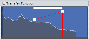
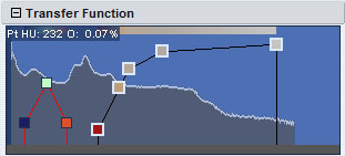
Figure 1: A simple transfer function.
The image in Figure 1 is taken from the transfer function editor from the Fovia Workstation application, and describes a simple transfer function. The horizontal axis in the image represents the scalar field values of the dataset. The values to the right equal more dense material and values to the left equal less dense material.
For example, in the case of CT data, the higher values (to the right) correlate with more dense material and values to the left correlate with less dense material. This is because the more dense material absorbs more X-Ray energy than the less dense material. In a CT scan, values to the right equal denser material like bone, while values to the left equal less dense material like soft tissue and skin. The vertical axis determines the opacity/translucency of voxels in the dataset. The bottom of the figure represents 0% opacity (100% transparent), the top of the figure represents 100% opacity. The gray histogram shows how many voxels of a given scalar value exist in the dataset. The two white dots make up a single render range and designate the color and position of the control points making up the transfer function. For this particular dataset, the position of the two control points corresponds to Hounsfield values (or other dataset units) of approximately 850 and 2250. Since the two control points are about halfway up the vertical axis of the chart, they represent opacity values of ~50%. The control points have been set to white, designating the color of the voxels within the HU 850 to HU 2250 range. Therefore, this transfer function maps all voxels with HU values between 850 and 2250 to white (RGB 255, 255, 255) and 50% opacity. All voxels outside this range are totally transparent and do not make any contribution. The resulting dataset image can be seen in Figure 2.
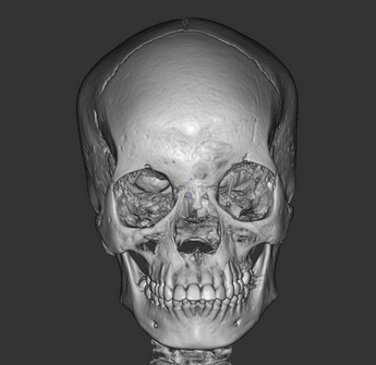
Figure 2: A dataset rendered with
the transfer function from Fig 1.
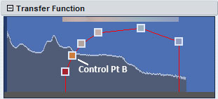
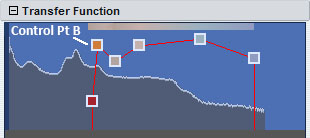
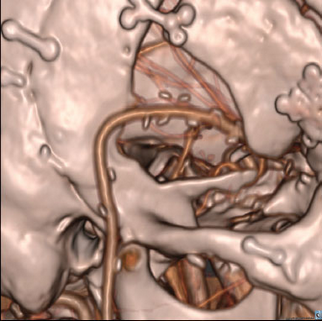
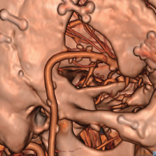
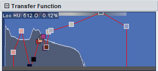
The images in Figures 3 and 4 show two different, slightly more complex transfer functions, with a single render range of six control points of varying opacity and color. In Figure 4, control point B has been raised slightly. This increases its opacity, and therefore increases the color contribution of voxels at or near that scalar value in the dataset. Figures 5 and 6 show a region of a sample dataset rendered with the transfer functions shown in Figures 3 and 4. The increased opacity of control point B in Figure 4 is evident in the darker orange color in Figure 6.
Figure 3: Control point B lower opacity.
|
Figure 4: Control point B higher opacity. |
Figure 5: Control point B lower opacity. |
Figure 6: Control point B higher opacity. |
A transfer function may have multiple continuous ranges of control points. Each transfer function can support up to eight separate render ranges, and each render range can support up to fifty control points. Figure 7 shows a transfer function with two separate render ranges. Control points in a transfer function also support a lighting state flag. The lighting state affects all voxels at that control point's scalar value up to the right-next control point. Thus, the lighting state for each interval between control points is determined by the left control point. Figures 8 and 9 show transfer functions with lighting turned off for some control points. Control points with a thick white border have lighting applied, control points with a thin black border do not have lighting applied. Control points in a transfer function also support a lighting state flag. The lighting state “ON” determines the usage of scalar field gradients for the calculation of the rendered image. Setting the lighting state to "ON" is useful for areas with surface-like structures (a coherent and rapid change of value of scalar field). Soft tissues are especially noisy and may contain foam-like data. It is often is more efficient and informative to render these soft tissues with the lighting state set to "OFF".
Figure 7: A transfer function with two render ranges and different lighting states. |
Figure 8: A transfer function with different lighting states. |
The opacity value of a given voxel indicates the percentage of the ray's energy that will be absorbed as the ray passes through the voxel, measured in increments of 1/16 of a dataset unit (usually millimeters). For example, if a voxel's opacity is 100% then after traveling 1/16th of a unit into the voxel, 100% of the ray's energy will be absorbed. If a voxel is 50% opaque and the ray travels horizontally through the center of the voxel, after the first 1/16th of a unit, 50% of the ray's energy will remain. After the next 1/16th of a unit, 25% of the energy will remain. Another 1/16th will leave 12.5%, and so on. When ray energy is absorbed it is converted to color based on the voxel's color value which is determined by the transfer function. Ray energy will be absorbed until so little energy remains that it can no longer contribute to the ray's color value. At this point the ray is considered to be 100% absorbed. For example, if a given ray has 100% of its original energy and it enters a voxel of 50% opacity, after passing 8/16th's (1/2) of a unit into the voxel then only 0.39% of it's energy will remain. Since RGB color is measured on a 0 to 255 scale, this will correlate to just under 1 color unit (0.39% * 255 = 0.99). At this point all the ray's energy will have been converted to color and the ray will stop. Note that the distance that a ray actually travels through a voxel depends on the angle at which a ray enters the voxel.
Consider the image in Figure 9. The first voxel has an opacity value of 0%, so no ray energy will be absorbed, regardless of the voxel's color. The next voxel is blue and 10% opaque. When the ray has finished traveling through the voxel, 18.5% of the energy will remain. The other 81.5% of the ray's energy will have been converted to blue, so its RGB color value will be (0, 0, 207) (81.5% * 255 = 207). The next voxel is green and 100% opaque. After traveling 1/16 of a unit into the voxel the remaining 18.5% of the ray's energy will be absorbed and converted to green, and the ray's color value will be (0, 47, 207) (18.5% * 255 = 47).
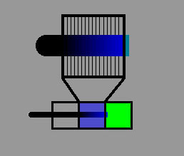
Figure 9: Ray traversal and absorption.
Implementing a Transfer Function
A single transfer function is defined with an array of eight RENDER_RANGE_PARAMS structures. Each RENDER_RANGE_PARAMS structure defines a set of up to fifty control points. The members of the RENDER_RANGE_PARAMS structure are shown in the table below.
COLORED_POINT aPnt[] |
An array of up to fifty COLORED_POINT control points which define the color and opacity of the points making up the transfer function. |
int iPnt |
The number of control points in the aPnt array. |
ENUM_RENDER_RANGE_STATUS Status |
A member of the ENUM_RENDER_RANGE_STATUS enumeration specifying if the render range is enabled or disabled. |
ENUM_RENDER_RANGE_TYPE Type |
A member of the ENUM_RENDER_RANGE_TYPE specifying the curve specified by the control points. Currently only RENDER_RANGE_TYPE_LINES is valid. |
Each COLORED_POINT control point specifies a color, opacity, and lighting flag. Together, the control points define a render range and specify the interpolated color and opacity values for rendering the voxels. The members of the COLORERD_POINT structure are shown in the table below.
h_int32 c |
The color of the control point in RGB. The lowest byte is red, the second byte is green and the third is blue. The fourth byte must be set to 0. This field can be set with the HDRC_RGBA() macro. |
h_int32 c2 |
Deprecated, do not use. |
h_int32 lighting1 |
Lighting value. 0 for lighitng on and 1 for lighting off. |
h_int32 lighting2 |
Deprecated, do not use. |
POINT pt |
This is the X, Y, coordinate of the point that determines its scalar value and opacity.
If RF_DONT_NORMALIZE_TF is set, x is the actual scalar value of the volume data being rendered. If RF_DONT_NORMALIZE_TF is not set, x is a value from 0-65535 representing a normalized range from 0% to 100% (0=0 and 100=65535).
The y value is a value from 0-4095 describing opacity. 0 is 0% opacity and 4095 is 100% opacity. 100% opacity means that over 1/16th of a volume unit (usually millimeters in CT), 100% of the ray energy will be absorbed. For example, if the opacity is 50% (2047) and the ray is traversing through a homogenous area of the value in this control point, then after 1/16th of a volume unit, 50% of the ray energy will remain and the rest will have been absorbed and accumulated as the color specified in c. After another 1/16th of a volume unit, 25% ray energy will remain. Another 1/16th will leave 12.5%...and so on.
Due to the nature of how volumes absorb energy as a ray is cast into it (described in the previous paragraph), the relationship between perceived opacity and this opacity value is logarithmic. So, a very small opacity value will still result in a very visible object. In many cases, it is appropriate to expose this value to the end user more linearly by applying something like the following calculation:
linearY = log2y |
h_int32 y2 |
Deprecated, do not use. |
A single transfer function is defined with an array of eight RENDER_RANGE_PARAMS structures. Each RENDER_RANGE_PARAMS structure defines a set of up to fifty control points. The members of the RENDER_RANGE_PARAMS structure are shown in the table below.
COLORED_POINT aPnt[] |
An array of up to fifty COLORED_POINT control points which define the color and opacity of the points making up the transfer function. |
int iPnt |
The number of control points in the aPnt array. |
int Status |
A member of the ENUM_RENDER_RANGE_STATUS enumeration specifying if the render range is enabled or disabled. |
int Type |
A member of the ENUM_RENDER_RANGE_TYPE specifying the curve specified by the control points. Currently only RENDER_RANGE_TYPE_LINES is valid. |
Each COLORED_POINT control point specifies a color, opacity, and lighting flag. Together, the control points define a render range and specify the interpolated color and opacity values for rendering the voxels. The members of the COLORERD_POINT structure are shown in the table below.
int c |
The color of the control point in RGB. The lowest byte is red, the second byte is green and the third is blue. The fourth byte must be set to 0. This field can be set with the HDRC_RGBA() macro. |
int c2 |
Deprecated, do not use. |
int lighting1 |
Lighting value. 0 for lighting on and 1 for lighting off. |
int lighting2 |
Deprecated, do not use. |
int x, y |
This is the X, Y, coordinate of the point that determines its scalar value and opacity.
If RF_DONT_NORMALIZE_TF is set, x is the actual scalar value of the volume data being rendered. If RF_DONT_NORMALIZE_TF is not set, x is a value from 0-65535 representing a normalized range from 0% to 100% (0=0 and 100=65535).
The y value is a value from 0-4095 describing opacity. 0 is 0% opacity and 4095 is 100% opacity. 100% opacity means that over 1/16th of a volume unit (usually millimeters in CT), 100% of the ray energy will be absorbed. For example, if the opacity is 50% (2047) and the ray is traversing through a homogenous area of the value in this control point, then after 1/16th of a volume unit, 50% of the ray energy will remain and the rest will have been absorbed and accumulated as the color specified in c. After another 1/16th of a volume unit, 25% ray energy will remain. Another 1/16th will leave 12.5%...and so on.
Due to the nature of how volumes absorb energy as a ray is cast into it (described in the previous paragraph), the relationship between perceived opacity and this opacity value is logarithmic. So, a very small opacity value will still result in a very visible object. In many cases, it is appropriate to expose this value to the end user more linearly by applying something like the following calculation:
linearY = log2y |
int y2 |
Deprecated, do not use. |
Once an array of RENDER_RANGE_PARAMS has been defined, it can be applied using the IRenderEngineContext::SetTransferFunction() or IRenderQueue::SetTransferFunction() methods. These methods take two input parameters. The first is a zero based integer designating which transfer function is being set (0 for TF1, 1 for TF2, etc). The second parameter is the array of eight RENDER_RANGE_PARAMS defining the transfer function. If only transfer function 1 needs to be set, this can be done with the RENDER_PARAMS::RenderRanges field. See the Render Parameters section for more information on setting render parameters.
RENDER_RANGE_PARAMS rrp[8];
BCOM_ZEROMEMORY(rrp);
// Sets a single render range of two control points.
rrp[0].Type = RENDER_RANGE_TYPE_LINES;
rrp[0].Status = RENDER_RANGE_STATUS_ENABLED;
rrp[0].iPnt = 2;
rrp[0].aPnt[0].pt.x = 1220*16;
rrp[0].aPnt[0].pt.y = 512;
rrp[0].aPnt[0].c = HDRC_RGBA(248, 180, 128, 0);
rrp[0].aPnt[1].pt.x = 3500*16;
rrp[0].aPnt[1].pt.y = 4000;
rrp[0].aPnt[1].c = HDRC_RGBA(250, 250, 250, 0);
// Set values for render range indices 1-7 if desired.
// Apply to transfer function 1.
pRenderEngine->SetTransferFunction(0, rrp);
Once an array of RENDER_RANGE_PARAMS has been defined, it can be applied using the hdrcRenderEngineContext::setTransferFunction() or hdrcRenderQueue::setTransferFunction() methods. These methods take two input parameters. The first is a zero based integer designating which transfer function is being set (0 for TF1, 1 for TF2, etc). The second parameter is the array of eight RENDER_RANGE_PARAMS defining the transfer function. If only transfer function 1 needs to be set, this can be done with the RENDER_PARAMS::RenderRanges field. See the Render Parameters section for more information on setting render parameters.
RENDER_RANGE_PARAMS[] rrp = new RENDER_RANGE_PARAMS[8];
// Sets a single render range of two control points.
rrp[0].Type = hdrcDefines.RENDER_RANGE_TYPE_LINES;
rrp[0].Status = hdrcDefines.RENDER_RANGE_STATUS_ENABLED;
rrp[0].iPnt = 2;
rrp[0].aPnt[0].pt.x = 1220*16;
rrp[0].aPnt[0].pt.y = 512;
rrp[0].aPnt[0].c = 248 | (180 << 8) | (128 << 16);
rrp[0].aPnt[1].pt.x = 3500*16;
rrp[0].aPnt[1].pt.y = 4000;
rrp[0].aPnt[1].c = 250 | (250 << 8) | (0 << 16);
// Set values for render range indices 1-7 if desired.
// Apply to transfer function 1.
renderEngine.setTransferFunction(0, rrp);
RENDER_RANGE_PARAMS[] rrp = new RENDER_RANGE_PARAMS[8];
// Sets a single render range of two control points.
rrp[0].Type = hdrcDefines.__Fields.RENDER_RANGE_TYPE_LINES;
rrp[0].Status = hdrcDefines.__Fields.RENDER_RANGE_STATUS_ENABLED;
rrp[0].iPnt = 2;
rrp[0].aPnt[0].pt.x = 1220*16;
rrp[0].aPnt[0].pt.y = 512;
rrp[0].aPnt[0].c = 248 | (180 << 8) | (128 << 16);
rrp[0].aPnt[1].pt.x = 3500*16;
rrp[0].aPnt[1].pt.y = 4000;
rrp[0].aPnt[1].c = 250 | (250 << 8) | (0 << 16);
// Set values for render range indices 1-7 if desired.
// Apply to transfer function 1.
renderEngine.setTransferFunction(0, rrp);
The XStream HDVR SDK provides methods to shoot an individual ray, or a set of rays, into the dataset. These methods will return information about where and how the ray intersects the dataset. The ShootRay() methods are provided by the IRenderEngineContext class and are described in the ShootRay() table below. If using an IRenderQueue class, the IRenderEngineContext object can be accessed with the IRenderQueue::GetRenderEngineContext() method. The various ShootRay() methods return results in an array of either RAYSTOPINFO or RAYWALLINFO structures. The members of these structures are described in the tables below.
The render engine must be idle for the various IRenderEngineContext::ShootRay() methods to work. The IRenderEngineContext::ShootRay() methods will return an error if the render engine is busy when these methods are called.
ShootRay() Methods
Shoots rays into the volume and returns information about the first non-transparent voxel that the ray intersects with. The results are returned in an array of RAYSTOPINFO structures.
|
|
A version of ShootRay() which is approximately 50% faster than the standard ShootRay() method. This method does not return min/max data in the RAYSTOPINFO structure.
The ShootRayFast() method takes the same parameters as the ShootRay() method.
|
|
A version of ShootRay() that allows one to set the percentage of ray energy that must be absorbed before the ray stops. It also allows one to set the origin coordinate of the ray, and a direction of travel for the ray.
|
|
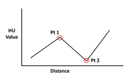
As a ray travels through a volume, the scalar value of the voxels the ray travels through tends to increase or decrease over measurable distances. The ShootRayGetWall() method can detect the inflection points at which the slope of the voxel's scalar gradient changes.
This method is used to determine the two points at which the visible voxel values in the dataset change slope (inflection points). For example, as a ray travels through the volume the voxel's scalar values may increase in value, then decrease, then increase again (or vice versa). The ShootRayGetWall() method will return data at the points where the voxel values first begin to decrease and then increase again. This is shown in the image below, the two returned points are shown in red. The ray will stop at the second marked point.
|
RAYSTOPINFO Fields
COLOR_RGBA Color |
Color of the voxel at which the ray stopped. |
short SubVolumeMax |
The maximum scalar value within the current transfer function's render range. |
short SubVolumeMin |
The minimum scalar value within the current transfer function's render range. |
short VoxelValue |
Scalar voxel value at the point where the ray stopped. |
VERTEX3D vtx |
Coordinates in volume coordinates where the ray stopped. |
h_int32 Reserved |
Reserved for future use. |
RAYWALLINFO Fields
h_boolean bValueGoesUp |
TRUE or FALSE depending on if the gradient increases or decreases after the first inflection point. |
RAYWALLSAMPLE Extremes [2] |
The voxel coordinates and values of the two detected points where the voxel value gradient changes slope. |
RAYSTOPINFO Stop |
The RAYSTOPINFO structure for the point where the ray stops (inflection point 2). |
The XStream HDVR SDK provides methods to shoot an individual ray, or a set of rays into the dataset. These methods will return information about where and how the ray intersects the dataset. The shootRay() methods are provided by the hdrcRenderEngineContext class and are described in the shootRay() table below. If using an hdrcRenderQueue class, the hdrcRenderEngineContext object can be accessed with the hdrcRenderQueue::getRenderEngineContext() method. The various shootRay() methods return results in an array of either RAYSTOPINFO or RAYWALLINFO structures. The members of these structures are described in the tables below.
The render engine must be idle for the various hdrcRenderEngineContext::shootRay() methods to work. The hdrcRenderEngineContext::shootRay() methods will return an error if the render engine is busy when these methods are called.
ShootRay() Methods
Shoots rays into the volume and returns information about the first non-transparent voxel that the ray intersects with. The results are returned in an array of RAYSTOPINFO structures.
|
|
A version of shootRay() which is approximately 50% faster than the standard shootRay() method. This method does not return min/max data in the RAYSTOPINFO structure.
The shootRayFast() method takes the same parameters as the shootRay() method.
|
|
hdrcRenderEngineContext::shootRay() (overload) |
A version of shootRay() that allows one to set the percentage of ray energy that must be absorbed before the ray stops. It also allows one to set the origin coordinate of the ray, and a direction of travel for the ray.
|
As a ray travels through a volume, the scalar value of the voxels the ray travels through tends to increase or decrease over measurable distances. The shootRayGetWall() method can detect the inflection points at which the slope of the voxel's scalar gradient changes.
This method is used to determine the two points at which the visible voxel values in the dataset change slope (inflection points). For example, as a ray travels through the volume the voxel's scalar values may increase in value, then decrease, then increase again (or vice versa). The shootRayGetWall() method will return data at the points where the voxel values first begin to decrease and then increase again. This is shown in the image below, the two returned points are shown in red. The ray will stop at the second marked point.
|
RAYSTOPINFO Fields
short SubVolumeMax |
The maximum scalar value within the current transfer function's render range. |
short SubVolumeMin |
The minimum scalar value within the current transfer function's render range. |
short VoxelValue |
Scalar voxel value at the point where the ray stopped. |
VERTEX3D vtx |
Coordinates in volume coordinates where the ray stopped. |
long Reserved |
Reserved for future use. |
RAYWALLINFO Fields
boolean bValueGoesUp |
TRUE or FALSE depending on if the gradient increases or decreases after the first inflection point. |
RAYWALLSAMPLE Extremes [2] |
The voxel coordinates and values of the two detected points where the voxel value gradient changes slope. |
RAYSTOPINFO Stop |
The RAYSTOPINFO structure for the point where the ray stops (inflection point 2). |
The speed with which the XStream HDVR SDK can render images is in large part dependent on the complexity of the transfer functions in effect. Consider the following issues when designing a transfer function:
| • | Translucent voxels are considerably more computationally complex to render then completely opaque voxels. If a ray has to traverse many voxels with low opacity it will be more computationally intense to calculate that ray's color. Therefore, it is recommended to avoid unnecessary use of transfer function settings with low opacity. |
| • | Turning off lighting for transfer function control points will significantly accelerate rendering. This is because the normal gradients at the dataset's virtual surface can be ignored. The rendering algorithm therefore does not need to traverse the entire octree down to individual voxels. Consequently, it is recommended to turn off lighting for transfer function control points where not necessary. |