Summary
When visualizing a volume dataset, it may often be beneficial to crop or cut away a portion of the volume. Cropping is frequently done to remove material that is not of clinical interest, and to improve the visualization of the target area of interest. Regions of the dataset that have been cropped are not processed or visualized by the rendering algorithm. The XStream® HDVR® SDK provides two methods of cropping a dataset: these are Slab Navigation and Cut Planes. The Slab Navigation feature visualizes only voxels that are within a set distance from the viewpoint. The Cut Planes feature allows up to sixteen separate planes to be defined that cut away regions of the dataset.
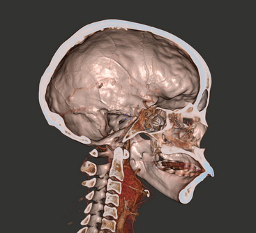
Slab navigation in parallel TF mode. |
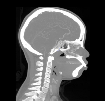
Slab navigation in MPR mode. |
Slab navigation is the most common manner used to display and navigate a portion of the volume. The slab defines a sub-section of the volume that is currently visible on screen. The front and back positions of the slab can be manipulated independently to control this area of visibility, as well as the size of the slab being displayed on the screen. The front of the slab is defined by the view position and orientation. The back of the slab is defined by the slab thickness. During a rendering operation, light rays extend from the view position into the volume to a maximum distance defined by the slab thickness.
Control of the slab thickness is useful for MIP, MinIP, and MPR rendering modes because it constrains the ray calculations to a subset of the volume, accelerating rendering and ensuring that the rendered voxel values are focused on the area of interest. Slab navigation is only available in parallel projection modes. The back clipping plane must be on to use slab navigation. The front clipping plane must be on if the viewpoint is to be placed inside the volume. Turning off the front clipping plane will ensure that the viewpoint is always outside the volume. This may be desirable if mouse navigation is being used to control the viewpoint.
Slab navigation is turned on and off using the RF_USE_SLAB_PAR, RF_USE_SLAB_MIP and RF_FRONT_CLIPPING_PLANE_ENABLED bitflags in the RENDER_PARAMS::Flags and RENDER_PARAMS::FlagsMask fields. The slab thickness is controlled by the RENDER_PARAMS::SlabThickness field. The front clipping plane is turned on and off with the RF_FRONT_CLIPPING_PLANE_ENABLED bit. This bit must be on if the viewpoint is positioned inside the volume. The back clipping plane is turned on and off with the RF_USE_SLAB_PAR and RF_USE_SLAB_MIP bits. The distance from the front clipping plane to the back clipping plane (the slab thickness) is controlled with the RENDER_PARAMS::SlabThickness field. The maximum recommended slab thickness value for Brute Force Rendering mode is 50 and the maximum supported value for the Adaptive Rendering mode is 4096. The dataset units are as specified in the volume specification. Voxel width/height/depth can be found in VOLUME_DATA_PARAMS::Spacing field.
RENDER_PARAMS rp;
BCOM_ZEROMEMORY(rp)
// Slab navigation is turned on as follows.
// Turn on the front and back clipping planes.
rp.FlagsMask = (ENUM_RENDER_FLAGS)(RF_FRONT_CLIPPING_PLANE_ENABLED | RF_USE_SLAB_PAR);
rp.Flags = (ENUM_RENDER_FLAGS)(RF_FRONT_CLIPPING_PLANE_ENABLED | RF_USE_SLAB_PAR);
// specify a slab thickness.
rp.Mask = (ENUM_RENDER_PARAMS_MASK)(RPM_SLAB_THICKNESS);
rp.SlabThickness = 50;
// Apply slab parameters.
renderEngine->SetRenderParams(&rp);
RENDER_PARAMS rp;
BCOM_ZEROMEMORY(rp)
// Slab navigation is turned off as follows.
// Clear the mask, since no changes to the rendering mask are required.
rp.Mask = 0;
// Set the FlagsMask bits to on, so the Flags fields will be read.
rp.FlagsMask = (ENUM_RENDER_FLAGS)(RF_FRONT_CLIPPING_PLANE_ENABLED | RF_USE_SLAB_PAR);
// Clear the Flags bits to turn off the front and back clipping planes.
rp.Flags = 0;
// Apply slab parameters.
renderEngine>SetRenderParams(&rp);
Slab navigation is turned on and off using the RF_USE_SLAB_PAR, RF_USE_SLAB_MIP and RF_FRONT_CLIPPING_PLANE_ENABLED bitflags in the RENDER_PARAMS.Flags and RENDER_PARAMS.FlagsMask fields. The slab thickness is controlled by the RENDER_PARAMS.SlabThickness field. The front clipping plan is turned on and off with the RF_FRONT_CLIPPING_PLANE_ENABLED bit. This bit must be on if the viewpoint is positioned inside the volume. The back clipping plane is turned on and off with the RF_USE_SLAB_PAR and RF_USE_SLAB_MIP bits. The distance from the front clipping plane to the back clipping plane (the slab thickness) is controled with the RENDER_PARAMS.SlabThickness field. The maximum recommended slab thickness value for Brute Force Rendering mode is 50 and the maximum supported value for the Adaptive Rendering mode is 4096. The units are as specified in the volume specification. Voxel width/height/depth can be found in VOLUME_DATA_PARAMS::Spacing field.
RENDER_PARAMS rp = new RENDER_PARAMS();
// Slab navigation is turned on as follows.
// Turn on the front and back clipping planes.
rp.FlagsMask = hdrcDefines.RF_FRONT_CLIPPING_PLANE_ENABLED | hdrcDefines.RF_USE_SLAB_PAR;
rp.Flags = hdrcDefines.RF_FRONT_CLIPPING_PLANE_ENABLED | hdrcDefines.RF_USE_SLAB_PAR;
// specify a slab thickness.
rp.Mask = hdrcDefines.RPM_SLAB_THICKNESS;
rp.SlabThickness = 50;
// Apply slab parameters.
renderEngine.setRenderParams(rp);
RENDER_PARAMS rp = new RENDER_PARAMS();
// Slab navigation is turned off as follows.
// Clear the mask, since no changes to the rendering mask are required.
rp.Mask = 0;
// Set the FlagsMask bits to on, so the Flags fields will be read.
rp.FlagsMask = hdrcDefines.RF_FRONT_CLIPPING_PLANE_ENABLED | hdrcDefines.RF_USE_SLAB_PAR;
// Clear the Flags bits to turn off the front and back clipping planes.
rp.Flags = 0;
// Apply slab parameters.
renderEngine.setRenderParams(rp);
RENDER_PARAMS rp = new RENDER_PARAMS();
// Slab navigation is turned on as follows.
// Turn on the front and back clipping planes.
rp.FlagsMask = hdrcDefines.__Fields.RF_FRONT_CLIPPING_PLANE_ENABLED | hdrcDefines.__Fields.RF_USE_SLAB_PAR;
rp.Flags = hdrcDefines.__Fields.RF_FRONT_CLIPPING_PLANE_ENABLED | hdrcDefines.__Fields.RF_USE_SLAB_PAR;
// specify a slab thickness.
rp.Mask = hdrcDefines.__Fields.RPM_SLAB_THICKNESS;
rp.SlabThickness = 50;
// Apply slab parameters.
renderEngine.setRenderParams(rp);
RENDER_PARAMS rp = new RENDER_PARAMS();
// Slab navigation is turned off as follows.
// Clear the mask, since no changes to the rendering mask are required.
rp.Mask = 0;
// Set the FlagsMask bits to on, so the Flags fields will be read.
rp.FlagsMask = hdrcDefines.__Fields.RF_FRONT_CLIPPING_PLANE_ENABLED | hdrcDefines.__Fields.RF_USE_SLAB_PAR;
// Clear the Flags bits to turn off the front and back clipping planes.
rp.Flags = 0;
// Apply slab parameters.
renderEngine.setRenderParams(rp);
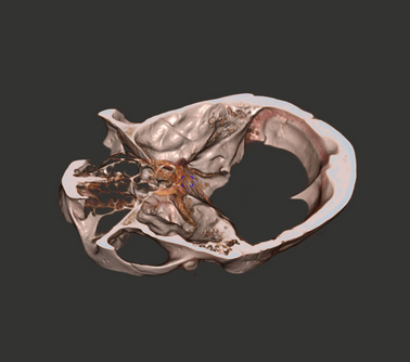
Cut planes used to visualize a portion of the skull.
Cut planes are another method used to visualize a subset of the volume. A cut plane defines a plane that cuts away all voxels on the underside of the plane. A cut plane can be used to cut away an unwanted portion of the volume, such as a scanning gantry or other material irrelevant to the region of interest. The XStream HDVR SDK supports up to 16 simultaneous cut planes.
A cut plane is defined with the CUT_PLANE_PARAMS structure. This structure includes a PLANEEQF plane definition, a member of the ENUM_CUT_PLANE_STATUS enumeration, and a member of the ENUM_CUT_PLANE_TYPE enumeration. The PLANEEQF structure defines a cut plane using a parametric equation of the form ax + by + cz = d. The C3DHelpers::GetPlaneEquation() utility function can be used to define a cut plane by designating three points on the plane. The ENUM_CUT_PLANE_STATUS member can be set to CUT_PLANE_STATUS_ENABLED to enable the cut plane, or CUT_PLANE_STATUS_DISABLED to disable the plane. The ENUM_CUT_PLANE_TYPE member designates the type of plane: currently only CUT_PLANE_TYPE_POSITIVE can be used for this member.
| • | If you run a point (x,y,z) through the equation ax + by + cz + d, the result will be 0 if the point is on the plane, negative if it’s behind the plane, and positive if it’s in front of the plane. |
| • | The vector described by (a,b,c) is the normal to the plane. |
| • | The constant d is the minimum distance of the plane from the origin. |
| • | When initialized, the first six cut planes in the render parameters structure are set to be parallel to the principal planes and one unit away from each of them. For C++, you can see the initialization of planes in sharedstructs.h file under the RENDER_PARAMS::SetDefaults() function. |
RENDER_PARAMS rp;
BCOM_ZEROMEMORY(rp);
// These three points define an X,Y plane.
VECTOR3D pt1 = VECTOR3D(0,0,0);
VECTOR3D pt2 = VECTOR3D(1,0,0);
VECTOR3D pt3 = VECTOR3D(0,1,0);
C3DHelpers hdrc3DHelpers;
PLANEEQF plane;
// Get a PLANEEQF parametric definition from the three points.
hdrc3DHelpers.GetPlaneEquation(&plane, &pt1, &pt2, &pt3);
// Set the mask so the CutPlanes field will be read.
rp.Mask = RPM_CUT_PLANES;
// Apply the plane to CutPlanes[0]
rp.CutPlanes[0].Plane = plane;
rp.CutPlanes[0].Status = CUT_PLANE_STATUS_ENABLED;
rp.CutPlanes[0].Type = CUT_PLANE_TYPE_POSITIVE;
// Apply the plane definition to the render engine.
renderEngine->SetRenderParams(&rp);
A cut plane is defined with the CUT_PLANE_PARAMS structure. This structure includes a PLANEEQF plane definition, a Status member and a Type member. The PLANEEQF structure defines a cut plane using a parametric equation of the form ax + by + cz = d. The hdrc3DHelpers::getPlaneEquation() utility function can be used to define a cut plane by designating three points on the plane. The Status member can be set to CUT_PLANE_STATUS_ENABLED to enable the cut plane, or CUT_PLANE_STATUS_DISABLED to disable the plane. The Type member designates the type of plane, currently only CUT_PLANE_TYPE_POSITIVE can be used for this member.
| • | If you run a point (x,y,z) through the equation ax + by + cz + d, the result will be 0 if the point is on the plane, negative if it’s behind the plane, and positive if it’s in front of the plane. |
| • | The vector described by (a,b,c) is the normal to the plane. |
| • | The constant d is the minimum distance of the plane from the origin. |
| • | When initialized, the first six cut planes in the render parameters structure are set to be parallel to the principal planes and one unit away from each of them. |
RENDER_PARAMS rp = new RENDER_PARAMS;
// These three points define an X,Y plane.
VECTOR3D pt1 = new VECTOR3D(0,0,0);
VECTOR3D pt2 = new VECTOR3D(1,0,0);
VECTOR3D pt3 = new VECTOR3D(0,1,0);
// Get a PLANEEQF parametric definition from the three points.
PLANEEQF plane = hdrc3DHelpers.getPlaneEquation(pt1, pt2, pt3);
// Set the mask so the CutPlanes field will be read.
rp.Mask = hdrcDefines.RPM_CUT_PLANES;
// Apply the plane to CutPlanes[0]
rp.CutPlanes[0].Plane = plane;
rp.CutPlanes[0].Status = hdrcDefines.CUT_PLANE_STATUS_ENABLED;
rp.CutPlanes[0].Type = hdrcDefines.CUT_PLANE_TYPE_POSITIVE;
// Apply the plane definition to the render engine.
renderEngine.setRenderParams(rp);
RENDER_PARAMS rp = new RENDER_PARAMS;
// These three points define an X,Y plane.
VECTOR3D pt1 = new VECTOR3D(0,0,0);
VECTOR3D pt2 = new VECTOR3D(1,0,0);
VECTOR3D pt3 = new VECTOR3D(0,1,0);
// Get a PLANEEQF parametric definition from the three points.
PLANEEQF plane = hdrc3DHelpers.getPlaneEquation(pt1, pt2, pt3);
// Set the mask so the CutPlanes field will be read.
rp.Mask = hdrcDefines.__Fields.RPM_CUT_PLANES;
// Apply the plane to CutPlanes[0]
rp.CutPlanes[0].Plane = plane;
rp.CutPlanes[0].Status = hdrcDefines.__Fields.CUT_PLANE_STATUS_ENABLED;
rp.CutPlanes[0].Type = hdrcDefines.__Fields.CUT_PLANE_TYPE_POSITIVE;
// Apply the plane definition to the render engine.
renderEngine.setRenderParams(rp);